- Welcome To Changzhou Huarui Welding & Cutting Machinery Co., Ltd.!
- About Huarui | Inquiry Form | Contact Us |
 中文
中文
中文

Innovation · Precision · Dependability
Engineered for Welders, Endorsed by Global Industry
We are not designing just another ordinary welding torch, but a product that endows welders with a sense of pride, control and creativity.
LOVE YOUR WELDING MOMENT.
Embrace every moment of welding.
HuaRui Welding & Cutting
From Made‑in‑China to the Global Stage.
We power the future of welding with innovation,
forge industrial excellence with precision,
and earn worldwide trust with reliability.
HuaRui Welding & Cutting is bringing China’s welding and cutting technologies to a broader international industrial arena.
We are committed to setting the GOAT standard for the welding industry,
making every weld glow with the radiance of global industrial progress.
From:NICKS
You are cordially invited to the 2026 Beijing Essen Welding & Cutting Fair.
Join HuaRui to explore the next‑generation welding innovations.
Consumables (tips, nozzles) wear rapidly
Arc becomes unstable, compromising weld quality
Torch handle overheats, causing operator fatigue or burns
Risk of torch damage or failure increases
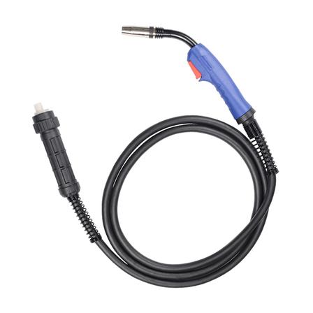
Lightweight & Portable: Compact design with no external cooling hoses, ideal for mobile or field welding.
Simple Operation: Plug‑and‑play setup with no additional cooling equipment required.
Low Maintenance: Fewer components to service; no coolant checks or leaks.
Cost‑Effective: Lower upfront cost and reduced long‑term maintenance expenses.
MIG Torches: Up to 250–300A (60% duty cycle).
TIG Torches: Up to 200–250A.
Ideal For:
Light to medium‑duty welding
Intermittent or short‑duration jobs
Repair, maintenance, and on‑site work
Confined spaces or hard‑to‑reach areas
MIG: HR‑25AK, HR‑24KD, HR‑15AK

TIG: WP‑9, WP‑26

Superior Cooling: Handles 350A+ continuous welding (100% duty cycle).
Extended Consumable Life: Lower operating temperatures reduce wear on tips and nozzles.
Operator Comfort: Cooler handle temperatures during long welds.
High‑Duty Performance: Stable arc and consistent weld quality in heavy industrial settings.
MIG Torches: 350A–500A (100% duty cycle).
TIG Torches: 300A–500A.
Ideal For:
Heavy‑duty manufacturing (shipbuilding, automotive, aerospace)
Long‑duration, high‑current welding
Automated or robotic welding systems
Thick metal fabrication
| Feature | Air‑Cooled | Water‑Cooled |
|---|---|---|
| Cooling Method | Natural convection + shielding gas | Closed‑loop water circulation |
| Weight | Lightweight | Heavier (with hoses) |
| Portability | Excellent | Limited |
| Max Current | ≤300A (MIG) | ≥350A (continuous) |
| Duty Cycle | 60% | 100% |
| Maintenance | Minimal | Regular coolant checks |
| Cost | Lower upfront & ongoing | Higher upfront & maintenance |
| Best For | Light/medium, intermittent work | Heavy‑duty, continuous work |
High‑Grade Copper Alloys: Enhanced thermal conductivity for efficient heat transfer.
Ergonomic Insulated Handles: Reduce heat transfer and operator fatigue.
Optimized Coolant Paths (water‑cooled): Targets high‑heat zones (neck, tip) for maximum cooling.
Robust Construction: Durable components to withstand harsh industrial environments.
Global Certifications: CE, ISO9001, and RoHS compliant for quality and safety.
Select Air‑Cooled If:
You work in mobile or field settings.
Welding current is ≤300A.
Jobs are intermittent or short‑duration.
Budget is a priority.
Select Water‑Cooled If:
You need continuous, high‑current welding (≥350A).
Working in heavy‑duty manufacturing or automation.
Extended weld times are common.
Maximizing consumable life and weld quality is critical.
Physical injuries: Strong arc light and ultraviolet rays burn eyes and skin; high-temperature molten slag causes scalds; spatter leads to cuts.
Electric shock risk: Electric leakage of welding machines, damaged cables and operation in humid environments may cause electric shock accidents.
Fire and explosion: Sparks and molten slag ignite flammables; contact with gas cylinders, oil drums or closed containers may lead to explosions.
Occupational hazards: Long-term inhalation of welding fumes, manganese, fluorides, ozone and other substances may cause pneumoconiosis and respiratory diseases.
Other risks: Falls during high-altitude operation, poisoning or suffocation in confined spaces, crushing injuries caused by falling workpieces.
Head and face protection
Auto-darkening welding helmets must be used. Sunglasses and plain glass are strictly prohibited as substitutes.
Protect against head impact, arc burns and molten slag splashing into eyes.
Respiratory protection
Wear dust masks or gas-proof half masks for routine operations.
Use supplied-air respirators in confined spaces or poorly ventilated areas to prevent inhalation of toxic fumes.
Body protection
Wear flame-retardant, wear-resistant and anti-static welding overalls, preferably made of thick dark cotton.
Do not wear chemical fiber clothes, short sleeves, shorts or sandals during operation to avoid arc burns and molten slag scalds.
Hand and foot protection
Wear **high-temperature resistant and wear-resistant special leather welding gloves`. Do not use worn or wet gloves.
Wear anti-smashing, insulated and high-temperature resistant safety shoes to protect feet from smashing, scalding and electric shock.
Operating environment cleaning
Before welding, remove all flammable and explosive materials within 5 meters of the working area, such as paint, gasoline, wood and gas cylinders.
For high-altitude welding, fire buckets and fire blankets shall be installed to prevent sparks from falling and causing fires.
Ventilation and isolation
Priority shall be given to mechanical ventilation and local exhaust to reduce the concentration of welding fumes.
When working in public areas or workshop passages, welding protection screens shall be installed to prevent arc light from harming others.
Confined space operation
The principle of ventilate first, detect then, operate last must be implemented.
Assign special personnel for supervision and rotate regularly. Working alone in a closed container is strictly prohibited.
The welding machine must be reliably grounded with qualified grounding resistance to prevent electric leakage.
Welding cables and grounding wires shall be free of **damage, exposure and excessive joints`. Overloading is prohibited.
No unprotected open-air operation in humid, rainy or waterlogged environments.
When replacing electrodes or adjusting parameters, keep hands dry and avoid direct contact with live parts.
After operation, turn off the welding machine switch first, then cut off the main power supply.
Oxygen cylinders, acetylene cylinders, argon cylinders and others shall be **stored separately and fixed vertically`. Falling, exposure to the sun and impact are strictly prohibited.
The distance between oxygen and acetylene cylinders shall be no less than 5 meters, and no less than 10 meters from open flames.
Welding oil drums, storage tanks or closed pipelines that are not thoroughly cleaned is strictly prohibited to prevent residual gas explosion.
The operation site must be equipped with emergency equipment such as fire extinguishers, fire sand and fire water.
In case of fire, cut off the power supply and stop operation immediately, use appropriate fire extinguishers. Blindly using water to put out electrical fires is prohibited.
Develop good operating habits: try to weld on the upwind side to reduce fume inhalation.
Take regular occupational health examinations, focusing on lungs, respiratory tract and eyes.
Avoid long-time continuous high-intensity work; take proper breaks to reduce occupational disease risks.
Enterprises shall be equipped with fume purification equipment, improve the working environment and fulfill the responsibility of occupational health protection.
Eye burn by arc light: stop working immediately, rest with eyes closed, use special eye drops, and seek medical treatment in serious cases.
Skin burns: apply cold compress in time, apply burn ointment and avoid infection.
Electric shock first aid: cut off the power supply before rescue. Do not pull the electric shock victim directly with bare hands.
Fire and explosion: call the police immediately, organize evacuation, and prioritize personal safety.
II. Key Points of Welding Technology
Selection of welding materials: Choose welding wires that match the chemical composition and mechanical properties of the base material, strictly control the impurity content, and ensure that the performance of the welded joint meets the requirements of nuclear-grade equipment.
Determination of welding process parameters: Determine appropriate parameters through process qualification tests. At the same time, adjust the parameters according to the pipe diameter and wall thickness to ensure good weld fusion.
Design and processing of bevels: Use appropriate bevel forms to ensure root penetration and weld formation. Commonly used are single-sided V or single-sided U bevels. The processing accuracy of the bevels is high, and the surface roughness is low to avoid impurity residues.
Control of welding environment: Welding should be carried out in a clean and dry environment. Before welding, the surfaces of the heat exchange tubes and tube sheets should be cleaned.
III. operation process and quality control Before welding preparation: strictly inspect the pipe and tube plate, clean the oil, rust and other impurities in the groove and nearby area. When the group is matched, the gap is uniform, and the extension or shrinkage of the tube head meets the requirements of the drawings and welding process. Bottom welding of the first layer: bottom welding is the key, the use of small current, short arc operation to ensure that the root of the groove is completely fused to ensure the penetration requirements. In order to obtain good penetration requirements, the method of increasing welding current is often used, but the structure is small in size, the weld is annular, the welding Angle of each point changes very fast, and the groove is unilateral structure. The welding operation with large current often causes excessive heat input, and the cover does not completely melt the root area of the groove when the liquid metal flows, resulting in local poor fusion and substandard penetration. Reduce the effective bearing thickness of the weld. Therefore, in the welding process of the first layer, a small standard current welding operation should be used to keep the distance between the tungsten pole and the molten pool constant, adjust the Angle of the welding torch according to the position of each point, so that the tungsten extreme head always points to the root of the groove, the welding speed is uniform, and the welding torch does a small horizontal swing to ensure that the welding arc is swept to all positions of the root of the groove and good fusion. The entire operation process can be self-melting or a small amount of welding wire. Prevent the formation of narrow and deep weld forms.
Filler welding: After the bottom welding is completed, clean the weld surface and the argon-coated groove with a wire brush for filler welding. The welding current increases relative to the first layer welding. The filling layer welding should pay attention to interlayer fusion, follow the principle of melting and filling first, and cannot be over-filled because of improving production efficiency, resulting in poor fusion or even non-melting between layers. Ensure the thickness of the weld, reserve the appropriate depth for the cover welding, (about 0.5 mm) to ensure the surface of the weld is smooth and the width is uniform and beautiful. Cover welding: cover layer as a direct contact surface with the equipment operating medium, good weld corrosion resistance is the main direction of welding operation should be controlled, smooth weld surface is conducive to reducing the media in the operation of the equipment for a long time on the weld surface, and increase the corrosion time. At the same time, it should have a good surface forming to meet the subsequent detection requirements.
During operation, the interlayer temperature and welding heat input should be strictly controlled. In order to obtain a smooth surface, wide and narrow weld. In the welding process, it can be segmented welding and only welding the easiest operation area, which can effectively ensure the welding quality of tube plate joint, reduce the difficulty of operation, and improve production efficiency.
Quality inspection: After welding, the appearance inspection shall be carried out, and the weld surface shall not have cracks, pores, slag inclusion and other defects, and the residual height and width shall meet the standard. Use non-destructive testing methods, such as surface PT, weld RT, etc., to ensure weld quality. For unqualified welds, analyze the reasons, make repair plans, and repair strictly according to the requirements.

HUARUI alibaba shop:
https://topwelding.en.alibaba.com
https://czhuarui.en.alibaba.com

When it comes to choosing mold steel, P20, 718H, and H13 are commonly used options. Here's a comparison of these three types:
P20: P20 is a general-purpose mold steel that is widely used in the industry. It has good machinability, excellent polishability, and good toughness. P20 is suitable for low to medium volume production and molds with moderate complexity. This type of steel is often chosen for applications that don't require high wear resistance or extreme operating conditions.
718H: 718H is a pre-hardened mold steel known for its superior hardness, toughness, and wear resistance. It offers good dimensional stability and is suitable for high-volume production and molds with complex designs. 718H provides better performance under abrasive materials or processes compared to P20. It is commonly used in injection molding, die casting, and extrusion dies.
H13: H13 is a hot work tool steel that excels in high-temperature applications. It has excellent heat resistance, high hardness, and good toughness. H13 is typically used for molds subjected to high thermal stress, such as those used in aluminum and zinc die casting. It is also suitable for extrusion dies and injection molding applications involving high-temperature materials.
When choosing between P20, 718H, and H13, consider the following factors:
Production volume: P20 is suitable for low to medium volume production, while 718H and H13 are better suited for high-volume production.
Complexity of the mold design: If the mold has intricate features or complex cavities, 718H or H13 may be more appropriate due to their higher hardness and better dimensional stability.
Material being molded: Consider the properties of the material being molded, including its abrasive nature, temperature sensitivity, and corrosiveness. Materials with high abrasiveness or high-temperature requirements may benefit from 718H or H13.
Surface finish requirements: If achieving a high-quality surface finish is crucial, P20 and 718H are known for their good polishability. H13 may require additional steps to achieve the desired surface finish.
It's very important to consult with mold designers and materials experts who can assess your specific requirements and recommend the most suitable steel for your application.
1. Definition
(1). Deposited Metal
-Deposited Metal refers to the metal part formed on the welded parts after welding materials (such as welding, welding wires, etc.) during welding. It includes the metal formed after the welding material itself is melted. For example, in the handmade arc welding, the metal formed on the welded parts after welding is Deposited Metal.
-The chemical composition and performance of Deposited Metal depends on the ingredients of welding materials. For example, when welding with stainless steel electrodes, the Deposited Metal will have the characteristics of stainless steel, such as corrosion resistance.
(2). Weld metal
-Tramne metal refers to the metal part formed after welding on the welded parts. It includes the melting part of the melting metal and the welded parts in the welding process. In other words, welded metal is a metal formed by melting metal and welded mother material. For example, during welding of two steel plates, the weld metal contains not only the melting metal formed by the welding strip melting, but also the part of the edge of the steel plate under welding thermal part.
2. Difference
(1). Metropolitan difference
-The Deposited Metal: Its ingredients are mainly determined by welding materials. If the welding material is pure nickel welding, the main component of the Deposited Metal is nickel.
-Tramne metal: The composition is the result of Deposited Meta and welded mother material melting. For example, when welding low -carbon steel and stainless steel, the ingredients of welded metals are complex components after mixed with low -carbon steel and stainless steel and welding materials.
(2). Different performance
-Deposited Metal: Its performance mainly depends on the performance of welding materials. If the Deposited Meta formed by high -intensity box formed has a high strength.
-Tramne metal: Its performance is commonly affected by the performance of Deposited Meta and welded parent material. For example, when welding steel with different intensity levels, the intensity of welded metals will be between two steels and Deposited Metals.
3. Application and importance
(1). Welding quality assessment
-In the control of welding quality, the analysis of the Deposited Metal and welded metal is very important. By analyzing the chemical ingredients and performance of the Deposited metal, you can evaluate whether the welding material meets the requirements. The analysis of the weld metal can determine the overall quality of the welding joint, such as strength, toughness, and corrosion resistance.
(2). Welding process selection
-Che select the appropriate welding material according to the material and use requirements of the welded parts to obtain the ideal Deposited metal and welded metal. For example, in marine engineering, in order to ensure the corrosion resistance of the welded joint, the welding material that can form a Deposited Metal and welded metal with good corrosion resistance is needed.
The difference between understanding the seam metal and Deposited metal is essential for correct selection of welding materials, controlling welding quality, and ensuring the use of welds.

HUARUI alibaba shop:
https://topwelding.en.alibaba.com
https://czhuarui.en.alibaba.com

1. The composition is different: The 7075 series is mainly composed of zinc, with a composition ratio of up to 6%. The 6061 series is mainly composed of magnesium and silicon, with a lower total composition ratio.
2. The strength is different: In terms of strength, 7075 is stronger, not inferior to steel, but only slightly stronger, only slightly stronger than 6061.
3. The price is different: 7075 is the lightest and strongest aluminum material, and its price is also super expensive. 6061 is the most common aluminum material, lightweight, strong, and economical.
4. Practicality is different: 7075 contains a higher proportion of other metals, so welding and processing are more difficult. Its proportion is higher, so it is usually not used as a frame material. 6061 contains a lower proportion of other metals, so it can be made stronger and its wind resistance reduced through various shaping and processing techniques. It can even be drawn three times to reduce weight. Overall, 6061 is a better material.

HUARUI alibaba shop:
https://topwelding.en.alibaba.com
https://czhuarui.en.alibaba.com

The CO2 gas shielded welding machine is a machine, electric and gas integrated device. In the use process, problems occurring should be understood, analyzed and solved from three aspects. Generally, not welding as circuit fault, not welding well as mechanical fault, welding poorly as process problem or protection gas impurity, gas path problem and other reasons. This is the epitome of experience, while the latter two account for 90% of the total problems.
When users encounter unstable arc, poor welding effect, and other abnormal phenomena, do not prematurely determine that the CO2 welding machine has failed. The occurrence of these problems or abnormal phenomena is often due to the following factors: fuse melting, loosening of fastening parts, forgetting to turn on the switch, improper parameter adjustment, cable breakage, gas hose cracking and air leakage, damage to the CO2 welding gun, etc. These faults and abnormal phenomena can be eliminated by the user himself. If you encounter a circuit fault that cannot be eliminated, you can go to the local sales network for after-sales treatment. Now I will explain to you the problems that are easy to encounter in the welding process, the defects that are easy to produce in the weld seam and the preventive measures.
Pore
Causes (generally have nothing to do with the welding machine itself)
1. Damage or freezing of the flowmeter of the gas regulator;
2. The value of the gas flow setting is not matched;
3. The fault of the welded torch body;
4. The solenoid valve fails;
5. There are oil, dirt, rust, paint film or welding wire for too long;
6. The surface of the welding wire has rust or other quality defects.
Prevent measures
1. Replace the flow meter or heated the gas flow meter;
2. Adjust to the appropriate air flow value;
3. Replace the welding torch;
4. Replace the solenoid valve;
5. Clean up the surface of the mother material, the welding wire extends to the appropriate length ;
6. Replace the new welding wire.
Welding current is unstable
Causes
1. The input and output cable is too long and detailed caused by the current instability;
2. The phenomenon of damage and wear of the wire delivery mechanism;
3. The aging of the filament hose;
4. welding gun head Severe (or incorrect pores).
5. Severe wear of the conductive tuling (or the pores are wrong).
Prevent measures
1. If input and output cables are too long, use cables with larger wire diameters;
2. Replace the new wire sending mechanism;
3. Replace the new silk hose;
4. Replace the new welding gun head;
5. Replace the new guide mouth.
Sending silk instability
Causes
1, the wire hose resistance is large;
2.Improper adjustment of wire feeding pressure;
3, poor welding wire, welding wire cross, uneven diameter or hard bending;
4, the conductive nozzle specification is wrong or the inner diameter is too small;
5, the wire wheel has dirt;
6. The bending radius of the welding torch cable is small, and the bending radius should be greater than 300mm.
Preventive measures
1, clean the wire hose with compressed air or replace the wire hose;
2, adjust the pressure arm, select the appropriate wire feeding pressure;
3, choose good quality welding wire;
4. Select a conductive nozzle that matches the diameter of the welding wire;
5. Clean or replace the wire feed wheel in time;
6, welding as far as possible to make the torch cable straight.
Arc instability
Cause
1, the output voltage is unstable;
2. Unstable wire feeding;
3. 3, poor welding wire quality;
Preventive measures
1, try to keep the dry elongation of the welding wire unchanged;
2.Check wire feeding during welding to ensure smooth wire feeding;
3, select good wire quality welding wire;
The welding wire is glued to the conductive nozzle
Cause
1, the extension length of the welding wire is too small;
2, the gas flow is too small;
3, the spatter in the nozzle is not cleared in time;
4, welding parameters do not match.
Preventive measures
1, choose the appropriate dry elongation;
2, adjust the appropriate gas flow;
3, timely clean the spatter in the nozzle;
4, select the appropriate and matched welding parameters.
Welding spatter is large
Cause
1, welding current and voltage do not match;
2, the inductance does not match, the greater the general current the greater the inductance;
3.The welding wire is extended too long or too short;
4.There are rust and oil stains on the surface of the base metal and welding wire.
Preventive measures
1, adjust the matching current and voltage values;
2, adjust the appropriate inductance value according to the current;
3, choose the appropriate dry elongation;
4, clean the surface of the base metal or replace the new welding wire.
Crack in weld
Cause
1, welding wire or workpiece is not clean;
2, the quality of welding wire is not good;
3, the first welding seam is too thin;
4, the current and melting depth is too large.
Preventive measures
1, replace the new wire, clean the surface of the workpiece;
2, select good wire quality welding wire;
3, increase the width of the weld;
4, adjust the welding specification, control the penetration.
A serpentine bead appears during welding
Cause
1, the conductive nozzle wear seriously;
2.The conductive nozzle is loose;
3. The mouth of the wire feed tube is too large;
4, the dry elongation of the welding wire is too large;
5, welding wire straightening adjustment is not good.
Preventive measures
1, replace the new conductive nozzle;
2. Tighten the conductive nozzle;
3, regular maintenance and cleaning of wire feeding tube or replacement of new wire feeding tube;
4, choose the appropriate dry elongation;
5, adjust the scale of the pressure arm, choose the right pressure.
Lack of penetration
Cause
1, the welding current is small, the melting depth is shallow;
2, groove and gap size is unreasonable, blunt edge is too large;
3, the arc is too long;
4. Poor cleaning between layers and welding roots.
Preventive measures
1, adjust and select the appropriate welding current;
2. The design of groove and gap size should be reasonable.
3. Reduce arc length;
4. Clean the layers and welding roots.
Weld through
Cause
1, welding current is too large;
2, the welding parts heated too much;
3, the groove butt clearance is too large;
4, welding speed is slow, arc residence time is long, etc.
Preventive measures
1, select the appropriate current parameters;
2, when heating the welding parts, pay attention to the temperature should not be too high;
3, groove and clearance design should be reasonable;
5. Speed up the welding speed appropriately.

HUARUI alibaba shop:
https://topwelding.en.alibaba.com
https://czhuarui.en.alibaba.com

The welding wire has a hard bend
The welding wire will not produce hard bending during production, but will be bumped during handling so that the welding wire of the wire tray falls down, or the scattered wire will be wrapped to the wire tray manually.
The wire with a hard bend will be blocked before entering the gun after entering the wire feed wheel. If it enters the welding torch, it will also be blocked by the wire feeding hose or conductive nozzle, and it can not be welded, and the conductive nozzle will be burned when the welding current and voltage are too large.
When unpacking and installing the welding wire, carefully check the welding wire reel to ensure that the welding wire reel is intact and the welding wire is wrapped neatly before use. When transporting the welding wire, be careful to avoid damaging the welding wire tray and causing the welding wire to be scattered. When wrapping the scattered wire back to the welding wire tray, wear gloves to wrap it carefully to avoid hard bending.
The welding wire is corroded
The packaging of the welding wire is damaged during transportation, the welding wire storage is too damp, the humidity exceeds the standard, the storage time is too long, and the welding wire is stored after being touched by hand.
When welding, the corroded welding wire enters the wire feeder, the pressing wheel will slip, affecting the normal wire feeding. When the welding wire with corroded parts enters the welding gun, due to the increase in the diameter of the welding wire, it will be blocked by the conductive nozzle and cannot be welded. When the current is too large, the conductive nozzle will be burned, and the weld will be poorly formed and there is debris on the surface.
When opening the packaging of the welding wire, check whether the welding wire is rusty, and the rusty welding wire should be replaced in time to the welding wire library. The welding wire packaging shall not be damaged, the humidity of the welding wire library shall be controlled, the welding wire shall be stored 300mm away from the ground and the wall, so that the welding wire purchased first is used first, and the welding wire used is strictly prohibited to touch with hands.
The welding wire has uneven thickness or burrs
When producing welding wire, it is caused by unqualified wire drawing equipment.
During welding, when the welding wire with uneven thickness or burr enters the welding gun wire feed hose, it will have friction with the flexible tube wall and vibration. When the vibration gradually approaches the welding gun, the wire feed will be unstable, interrupted welding or stuck into the conductive nozzle.
Matters needing attention
If intermittent welding occurs after replacing the new conductive nozzle, check the welding wire before welding with a matching conductive nozzle. When it is found that the welding wire without the pressing wheel of the welding machine is not smooth through the conductive nozzle matching the model, it must be the diameter of the welding wire is not uniform, and the welding wire should be replaced.
Improper use of wire feed pressing wheel
When the wire feeding machine is used, the pressing wheel should be matched with the welding wire, the solid core carbon steel welding wire uses a steel wheel, the flux-cored welding wire uses a ceramic wheel, and the wheel groove model matches the diameter of the welding wire. The pressure shall be adjusted according to the requirements of use, and shall not be too loose or too tight.
When the carbon steel solid core welding wire uses the ceramic wheel, it will cause the ceramic wheel to wear too fast. When the flux-cored wire uses a steel wire feed wheel, the flux-cored wire will be crushed and cracked, and the flux will leak out and cannot be welded. When the diameter of the carbon steel solid wire is larger than the diameter of the groove of the wire feed wheel, it is easy to produce indentation on the wire, so that the circular section of the wire is deformed, and the welding wire with indentation will be stuck through the conductive nozzle. When the diameter of the wire is less than the diameter of the groove of the wire feed wheel, the friction between the wire feed wheel and the wire is insufficient, and the wire can not be fed normally. When the wire feed wheel and the diameter of the welding wire match, the wire feed machine pressing wheel pressure should also be appropriate. When the pressure of wire feed wheel is too large, the welding wire will be deformed. When the pressure of the wire feed wheel is too small, the friction between the wire feed wheel and the welding wire is too small, and the wire feed instability will occur when the welding wire is resisted in the wire feed hose or the conductive mouth.
According to the requirements of the use of steel or ceramic wire feed wheel, wire feed wheel groove type and diameter to match the wire, wire feed wheel pressure to be moderate, wire feed wheel groove to be cleaned frequently.
The bending of the welding gun is too large and too fast
Welding is too random or special weld space position makes the welding gun bend too much.
It will cause the welding wire to be blocked too much when running in the wire feed hose of the welding gun, resulting in wire difficulty and wire feeding instability.
During welding, the welding gun should be kept as straight or as bent as possible to reduce the running resistance of the welding wire in the wire feeding hose.
Grooves are ground in the welding gun wire feed spring hose
The use time of the welding gun wire feed spring hose is too long. When the welding wire passes through the wire feed hose, the inside of the hose will be worn out.
Cause phenomenon
During welding, when the welding wire enters the groove in the wire feed spring hose, the change of the bending degree of the welding gun will cause the phenomenon of wire clamping in the groove, which will hinder the normal operation of the wire feed.
When the wire feed spring hose is used for too long, the wire is not smooth, and the wire feed hose after the welding torch hand tremors or the wire blocking phenomenon occurs with the change of the Angle of the welding torch, the wire feed spring hose should be replaced in time. Try to keep a large bending Angle of the welding gun to reduce the friction of the welding wire in the wire feeding hose. The wire feed spring hose is too short in the welding gun, which will cause the welding wire to bend inside the welding gun, forming a poor wire feed. When the spring hose is too long inside the welding gun, it will bend, which will increase the friction resistance of the wire feed and cause the instability of the wire feed.
The conductive nozzle is not cleaned in time
When the welding specification is not properly adjusted, or the welding gun is too close to the welding pool, the welding splash sticks to the conductive mouth, and the longer the welding time, the more the adhesive splash.
The more splashing of the nozzle, the easier it is to block the wire hole of the nozzle, thereby increasing the resistance of wire feeding, resulting in unblocked welding wire or blocked wire phenomenon.
Adjust the Angle of the torch and the stretch length of the wire as required during welding to reduce spatter. Often use the needle-nose pliers to clean up the spatters on the conductive mouth. After cleaning up, extend the welding wire out of the conductive mouth 10~15cm long, bend the welding wire from the base of the conductive mouth with the needle-nose pliers, rotate it clockwise or counterclockwise 3~5 turns, and quickly loosen it. Use the power of the welding wire rotation to smooth the wire feed hole of the conductive mouth.
The wire feed hole of the conductive nozzle is too worn
In the welding process, the conductive nozzle after a long time of welding wire wear will cause the wire feed hole too large.
Cause phenomenon
The large feeding hole of the conductive nozzle will cause poor electrical conductivity during welding, and the discharge between the welding wire and the conductive nozzle will make the wire feed unstable or stick to the conductive nozzle, and the welding wire will swing back and forth in the welding pool, affecting the weld formation.
When welding, it is found that the welding wire swings back after the conductive nozzle, and is accompanied by adhesion to the conductive nozzle, and a new conductive nozzle should be replaced in time. The conductive nozzle of the welding gun should be matched with the diameter of the welding wire, and the diameter of the conductive nozzle is too small, resulting in excessive friction resistance, so that the welding wire is not smooth or blocked. Too large conductive nozzle will cause the welding wire to swing back and forth in the weld pool, resulting in poor weld formation.
Voltage and current do not match during welding
Not adjusted according to the specified welding specifications, lack of welding experience.
When the current is too large and the voltage is too small, intermittent unstable welding will occur, welding spatter is too large, and the sound of the welding wire transition to the weld pool is loud and chaotic. When the current is too small and the voltage is too large, the welding dust is too large, the transition sound of the welding wire to the melt pool is small, and the welding wire and the conductive nozzle are melted and stuck together at the same time, and can not be welded.
According to the production needs, adjust according to the welding specification, so that the welding wire into the melt pool in time, the welding wire to the melt pool transition sound uniform.
In addition to the above nine reasons, there may also be poor quality of the welding machine, unstable operation of the wire feed motor, the copper plating layer of the welding wire is not tightly combined, and copper powder is dropped, causing the conductive nozzle to be blocked, forming an unstable wire feed. The fixed shaft of the wire tray of the wire feeder is too loose, and too tight will cause the wire resistance to be too large and the wire is unstable. During welding, the loose ground wire or the contact rust is not cleaned, resulting in excessive resistance and unstable arc will affect wire feeding. The conductive nozzle is not tightened, resulting in unstable welding current and voltage and also unstable wire feeding.
The above experience can provide the judgment basis and solution for the instability of wire feeding in the operation of CO2 gas shielded welding, so as to improve production and product quality.

HUARUI alibaba shop:
https://topwelding.en.alibaba.com
https://czhuarui.en.alibaba.com


look forward to your coming

HUARUI alibaba shop:
https://topwelding.en.alibaba.com
https://czhuarui.en.alibaba.com

Welding of low carbon steel and low alloy steel
Low carbon steel and low alloy steel belong to ordinary ferritic steel, and the welding between them and the welding between low alloy steel of different materials belongs to the welding of the same heterogeneous steel. The welding between such steels is done according to the low-grade material, which refers to the material with low strength level or alloying element content, to ensure that the weld metal performance meets the low-grade material. The selection of low-grade materials also has better welding performance than high-grade materials, and the price is cheaper, which is conducive to reducing manufacturing costs.
Welding of low alloy and medium alloy steels
Because of the discontinuity of the chemical composition of the weld, the discontinuity of the performance will be produced. If this discontinuity has a greater impact on the performance of the service, the welding material can not be selected according to the low-grade principle.
For example, SA213-T91 and SA213-T22 material welding, if according to the usual low-grade principle, the selection of 2.25Cr-1MO welding material for welding, then the T91 base metal near the fusion line on the T91 side will be seriously carburized, resulting in a decarburized layer, and the weld near the fusion line on the T91 side will be seriously decarburized, resulting in a decarburized layer. This is because the chromium content of T91 is about 9%, and the carbon content of 2.25Cr-1Mo welding wire is about 2.25%. Then, after annealing treatment, the chromium content of the heat affected zone on the T91 side is far greater than that on the weld side, and a large amount of carbon will shift to the base material to produce a carburized layer, resulting in increased hardness, more hardened organization, and serious decarburization on the weld side. The hardness is low, the structure softens, and the joint performance deteriorates. If the 9Cr-1Mo welding material is selected, the weld carburization and decarburization of the base material will occur on the side of the T22 fusion line.
Welding material selection of dissimilar steel welding
For welding of carbon steel, low alloy steel and austenitic stainless steel, welding materials should be selected according to the working temperature of the joint and the stress condition of the joint.
When the working temperature of such dissimilar steel joints under bearing pressure is below 315 ° C, austenitic stainless steel welding materials with high Cr and Ni alloy content can be selected. According to the chemical composition of carbon steel (alloy steel) and austenitic steel and the size of the fusion ratio of welding, austenitic stainless steel welding materials with appropriate Cr and Ni content are selected according to a certain nickel equivalent and chromium equivalent microstructure diagram to avoid a large number of martensitic tissues in the weld. Of course, a narrow martensitic band will be produced near the fusion line of carbon steel or low alloy steel. By reducing the carbon content of the welding material, the martensitic structure is low carbon martensitic with good plasticity, and the joint can also ensure good performance.
When bearing and bearing dissimilar steel joints work at temperatures above 315 ° C, nickel-based welding materials should be selected. For example, ECrNiFe 2,ERCrNiFe 3, etc., the main reasons are as follows.
If the ordinary austenitic stainless steel welding material is selected, the following problems will occur:
a) Due to the large difference in the coefficient of thermal expansion between ferrite and austenite, thermal stress and thermal fatigue damage will occur when running at high temperatures.
b) Due to the large difference in alloying element content, welding joints working at high temperatures will produce serious decarburization layer and carburization layer, which deteriorates the high temperature performance.
c) Due to the martensitic band organization near the fusion line, the local tissue of the weld is hardened.
The selection of nickel-based welding materials can avoid the above phenomenon, for the following reasons:
a) The coefficient of thermal expansion of nickel-based materials is between ferrite and austenite.
b) Nickel-based materials do not produce decarburization and carburization when welded joints.
c) Welding of nickel-based materials will not produce martensitic structure.
However, for non-load-bearing welded joints under high temperature work, the selection of nickel-based electrode can meet the performance requirements, but the manufacturing cost is expensive, and there is no need to use. The use of other inexpensive welding materials can also achieve the purpose.
A large number of experimental studies abroad have shown that for the non-bearing fillet welds of pipes and accessories in boiler manufacturing, when the pipes are carbon steel and low alloy steel materials, and the accessories are austenitic stainless steel, the welding materials should be selected according to the low grade materials.

HUARUI alibaba shop:
https://topwelding.en.alibaba.com
https://czhuarui.en.alibaba.com

Sources and hazards of radiation
Thorium tungsten electrodes used in argon arc welding and plasma arc welding contain 1-1.2% thorium oxide, a radioactive substance that is affected by radiation during welding and contact with thorium tungsten rods.
Radiation acts on the human body in two forms: one is external irradiation, and the other is internal irradiation which occurs when it enters the body through the respiratory and digestive systems. From a large number of investigations and measurements of masked argon arc welding and plasma arc welding, it has been proved that their radioactive harm is small, because the consumption of thorium tungsten rods is only 100-200 mg per day, and the radiation dose is extremely small, which has little impact on the human body.
But there are two things to be aware of:
First, when welding in the container, the ventilation is not smooth, and the radioactive particles in the smoke may exceed the health standard;
Second, the concentration of radioactive aerosols and radioactive dust in the grinding of thorium tungsten rods and the locations where thorium tungsten rods are present can meet or even exceed health standards.
Radioactive substances into the body can cause chronic radiation disease, mainly in the general functional state weakened, you can see obvious weakness, resistance to infectious diseases significantly reduced, weight loss and other symptoms.
Measures to prevent radiation damage
(1) Thorium tungsten rod should have special storage equipment, a large number of storage should be hidden in the iron box, and installed exhaust pipe.
(2) When welding with a closed cover, the cover body should not be opened during the operation, and the air supply protective helmet or other effective measures must be worn during manual operation.
(3) Special grinding wheels should be provided to grind thorium tungsten rods, dust removal equipment should be installed in the grinder, and the grinding chips on the ground of the grinder should be often wet swept and intensively buried.
(4) Wear a dust mask when grinding thorium tungsten rod. Wash hands with running water and soap after contact with thorium tungsten rod, and wash clothes and gloves frequently.
(5) Select reasonable specifications when welding and cutting to avoid excessive burning of thorium tungsten rod.

HUARUI alibaba shop:
https://topwelding.en.alibaba.com
https://czhuarui.en.alibaba.com

1. Hydrogen embrittlement
Hydrogen embrittlement usually manifests as delayed fracture under stress. There have been galvanized parts such as automobile springs, washers, screws, and blade springs, which have broken in succession within a few hours after assembly, and the proportion of breakage has reached 40% to 50%. A special product cadmium plating parts in the use of the process has appeared batch crack fracture, has organized a national research, the development of strict hydrogen removal process. In addition, there are some hydrogen embrittlement does not show delayed fracture phenomenon, for example: electroplating hangers (steel wire, copper wire) due to multiple electroplating and pickling plating, hydrogen infiltration is more serious, and the phenomenon of embrittlement often occurs when a break occurs in use; A mandrel used for precision forging of a hunting gun, after several times of chromium plating, fell and broke; Some hardened parts (large internal stress) will crack when pickling. These parts are so heavily hydrogen-permeated that cracks occur without external stress, and it is no longer possible to use hydrogen removal to restore the original toughness.
2. Hydrogen embrittlement mechanism
The phenomenon of delayed fracture is caused by the diffusion and accumulation of hydrogen in the parts to the parts where the stress is concentrated, and there are many metal defects in the parts where the stress is concentrated (dislocation of atomic lattice, holes, etc.). Hydrogen diffuses to these defects, hydrogen atoms become hydrogen molecules, creating a huge pressure, this pressure and the residual stress inside the material and the external stress on the material, forming a resultant force, when this resultant force exceeds the yield strength of the material, resulting in fracture. Since hydrogen embrittlement is related to the diffusion of hydrogen atoms, diffusion takes time, and the speed of diffusion is related to the concentration gradient, temperature and material type. Therefore, hydrogen embrittlement usually appears as delayed fracture.
Hydrogen atom has the smallest atomic radius, and it is easy to diffuse in steel, copper and other metals, while it is difficult to diffuse hydrogen in cadmium, tin, zinc and their alloys. The cadmium plating layer is the most difficult to diffuse, and the hydrogen produced during cadmium plating, which initially stays in the coating and the metal surface beneath the coating, is difficult to diffuse outward, and dehydrogenation is particularly difficult. After a period of time, hydrogen diffuses into the metal, especially the hydrogen that enters the metal's internal defects, it is difficult to diffuse out. The diffusion rate of hydrogen at room temperature is quite slow, so it needs to be heated immediately to remove hydrogen. The temperature increases, increasing the solubility of hydrogen in steel, too high temperature will reduce the hardness of the material, so the stress before plating and the temperature of dehydrogenation after plating must be considered not to reduce the hardness of the material, not to be in the brittle tempering temperature of some steel, not to destroy the performance of the coating itself.
Measures for avoidance and elimination
1. Reduce the amount of hydrogen infiltration in the metal
When removing rust and oxidation, try to use sand blowing to remove rust, if using pickling, it is necessary to add rhodin corrosion inhibitor in the pickling solution; In the oil removal, the use of chemical oil removal, cleaning agent or solvent oil removal, less hydrogen infiltration, if the use of electrochemical oil removal, first cathode after anode; In electroplating, alkaline bath or bath with high current efficiency has less hydrogen infiltration.
2. Low hydrogen diffusivity and low hydrogen solubility of the plating coating
It is generally believed that when electroplating Cr, Zn, Cd, Ni, Sn, Pb, hydrogen infiltrated into steel parts is easy to remain, and Cu, Mo, Al, Ag, Au, W and other metal coatings have low hydrogen diffusion and low hydrogen solubility, and hydrogen infiltration is less. In the case of meeting the requirements of the technical conditions of the product, the coating that will not cause hydrogen infiltration can be used, such as dacromet coating layer can replace galvanized, will not occur hydrogen embrittenness, corrosion resistance is improved by 7 to 10 times, good adhesion, film thickness of 6 to 8um, equivalent to a thinner galvanized layer, does not affect the assembly.
3. Stress before plating and remove hydrogen after plating to eliminate hydrogen embrittlement
If the internal residual stress of the parts is large after quenching, welding and other processes, tempering treatment should be carried out before plating to reduce the hidden danger of serious hydrogen infiltration.
Parts with more hydrogen infiltration during electroplating should in principle be dehydrogenated as soon as possible, because the hydrogen in the coating and the hydrogen in the surface substrate metal are diffused into the steel substrate, and the amount increases with the extension of time. The new draft international standard states that "it is best to carry out dehydrogenation treatment within 1h after plating, but no later than 3h". There are also corresponding standards in China, which stipulate the dehydrogenation treatment before and after electrogalvanizing. The process of hydrogen removal after electroplating is widely used in heating and baking, and the commonly used baking temperature is 150 ~ 300℃, and the heat preservation is 2 ~ 24h. The specific treatment temperature and time should be determined according to the size of the part, strength, coating properties and the length of plating time. Dehydrogenation is usually carried out in an oven. The dehydrogenation treatment temperature of galvanized parts is 110 ~ 220℃, and the temperature control level should be based on the base material. For elastic materials, thin-walled parts below 0.5mm and steel parts with high mechanical strength requirements, hydrogen treatment must be carried out after galvanizing. In order to prevent "cadmium brittleness", the dehydrogenation treatment temperature of cadmium-plated parts can not be too high, usually 180 ~ 200℃.
Three, should pay attention to the problem
The greater the strength of the material, the greater its hydrogen embrittlement sensitivity, which is the basic concept that surface treatment technicians must be clear when preparing electroplating process specifications. International standards require steel with tensile strength σb>105kg/mm2 to be stressed before plating and dehydrogenated after plating. The French aviation industry requires corresponding dehydrogenation of steel parts with yield strength σs>90kg/mm2.
Because the strength of steel has a good correspondence with the hardness, it is more intuitive and convenient to judge the hydrogen embrittlement sensitivity of the material by the hardness of the material than by the strength. Because a perfect product drawing and machining process should be marked with steel hardness. In electroplating, we found that the hardness of steel began to show the risk of hydrogen embrittlement fracture when it was about HRC38. For parts higher than HRC43, dehydrogenation treatment should be considered after plating. When the hardness is about HRC60, it must be dehydrogenated immediately after the surface treatment, otherwise the steel will crack within a few hours.
In addition to steel hardness, the following points should also be considered:
(1) The use of safety factor of parts: parts with large safety importance should be strengthened to dehydrogen;
(2) The geometry of the parts: with a gap that is easy to produce stress concentration, parts such as small R should be strengthened to dehydrogen;
(3) Cross-sectional area of parts: small spring steel wire and thin blade spring are easily saturated with hydrogen, and dehydrogen should be strengthened;
(4) The degree of hydrogen infiltration of parts: in the surface treatment of more hydrogen, long processing time parts, should be strengthened to dehydrogen;
⑤ Type of coating: such as cadmium plating layer will seriously block hydrogen diffusion, so it is necessary to strengthen dehydrogenation;
The mechanical properties of parts in use: when the parts are subjected to high tensile stress, dehydrogen should be strengthened, and hydrogen embrittlement will not be produced only when the stress is compressed;
⑦ Surface processing state of parts: for parts with large internal residual stress such as cold bending, drawing, cold bending, quenching, welding, etc., it is not only necessary to strengthen dehydrogen after plating, but also to remove stress before plating;
⑧ Historical situation of parts: Special attention should be paid to parts that have been hydrogen embrittlement in the past production, and relevant records should be made.
Dehydrogen embrittlement
The main reason is the metal "hydrogenation" phenomenon caused by the electroplating process, and the unqualified products you use are not the plating process itself has a problem, because electroplating (except vacuum plating) will cause metal hydrogenation, but at present, many metal surface treatment providers have removed the last process (especially for elastic components are deadly) : That is the "dehydrogen treatment" process, that is to say, under normal circumstances, for metal parts with strength requirements need to be dehydrogenated before they can be handed to the user, but in order to save production costs, and the user does not understand the case or has never required, accepted the case, omitting this process can save 5~15% of the cost. So you feel that the bolts, spring washers and other parts after electroplating are "brittle" after electroplating treatment.
Generally speaking, the dehydrogenation treatment requirements for metal parts with strength requirements are: 120 degrees ~220 degrees high temperature maintained for 1 to 2 hours (after electroplating), and the specific

HUARUI alibaba shop:
https://topwelding.en.alibaba.com
https://czhuarui.en.alibaba.com

1 What is acid electrode?
Electrode containing more acid oxide in the coating, such as junction 422 (E4303), junction 502 (E5003) and other AC-DC dual electrode.
2 What is alkaline electrode?
The electrode containing a large amount of alkaline oxide and fluoride, such as junction 507 (E5015), junction 506 (E5016) and other electrodes.
3 What is cellulose type (downward vertical welding special) electrode?
Welding rod containing a large amount of organic matter in the coating, pipe and thin plate structure downward vertical welding.
< 1 > For example, E6010 (equivalent to E4310, J425G) is suitable for bottom welding, hot welding, fill welding.
< 2 > E8010 (equivalent to E5511, J555) is suitable for hot welding, filling welding, cover welding layer.
Generally use low hydrogen down electrode cover welding; E7048 (equivalent to J506X) weld is clean and beautiful.
4 Why should the electrode be strictly dried before welding?
The welding rod will often deteriorate the process performance due to moisture absorption, resulting in unstable arc, increased spatter, and easy to produce porosity, cracks and other defects. Therefore, the electrode must be strictly dried before use. The drying temperature of the general acid electrode is 150 ~ 200℃, and the time is 1 hour. The drying temperature of the alkaline electrode is 350 ~ 400℃, the time is 1 ~ 2 hours, and the electrode is placed in the insulated box of 100 ~ 150℃ after drying.
5 What is welding wire?
A wire used as a filler metal in welding and used to conduct electricity at the same time - called a welding wire. There are two kinds of solid wire and flux-cored wire. Common solid wire model: ER50-6 (grade: H08Mn2SiA).
6 What is flux-cored wire?
A kind of welding wire made by drawing a thin steel strip rolled into a round steel pipe, which is filled with a certain composition of powder.
7 Why is the flux-cored wire protected with CO2 gas??
There are two types of flux-cored wire according to the protection mode: flux-cored gas-protected wire and flux-cored self-protected wire. The flux-cored gas-protected welding wire is generally protected by CO2 gas, which belongs to the form of gas-slag combined protection. It has good weld forming and high comprehensive mechanical properties.
8 When is the welding material scrapped?
Corrosion of welding core, adhesion, peeling, serious moisture (especially low hydrogen type electrode, heat-resistant steel electrode, low-temperature steel electrode), such electrode can no longer be used, to be scrapped.
9 What are the effects of moisture on the electrode?
After the electrode is damp, the color of the general coating is dark, the collision of the electrode loses the crisp metal sound, and some even appear "white flowers".
Influence of damp electrode on welding process:
(1) The arc is unstable, the splash is increased, and the particles are too large.
(2) deep penetration, easy to bite edge.
(3) The slag is not covered well and the welding wave is rough.
(4) It is difficult to remove slag.
Influence of damp electrode on welding quality:
(1) Easy to cause welding cracks and pores, especially alkaline electrode.
(2) The values of mechanical properties are easy to be low.
10 What are the effects of damp welding wire?
Moisture absorbing welding wire can increase the content of diffused hydrogen in the deposited metal, resulting in pits, pores and other defects, welding process performance and mechanical properties of weld metal become worse, and serious weld cracking can be caused.
After nitriding, quenching and low temperature tempering are also required.

HUARUI alibaba shop:
https://topwelding.en.alibaba.com
https://czhuarui.en.alibaba.com

1.Anneal
1. Treatment Method:
The steel parts are heated to a temperature below Ac3 +30 ~ 50℃ or Ac1+30 ~ 50℃ or Ac1, and generally cooled slowly with the furnace after thorough burning and heat preservation.
2. Purpose:
① Reduce hardness, improve plasticity, improve cutting and pressure processing performance;
② Refine grain, improve mechanical properties, prepare for the next step;
③ Eliminate the internal stress caused by hot and cold processing.
3. Application:
① Applicable to alloy structural steel, carbon tool steel, alloy tool steel, high-speed steel and other forgings, welding parts and supply of unqualified raw materials;
② Generally annealed in blank state.
2. normalizing
1. Treatment Method:
The steel parts are heated to 30 ~ 50℃ above Ac3 or Accm, and the cooling rate is slightly greater than that of annealing after insulation.
2. Purpose:
The purpose of normalizing is similar to annealing.
3. Application:
Normalizing is usually used as a pre-heat treatment process for forgings, welds and carburized parts. For low carbon and medium carbon carbon structural steel and low alloy steel parts with low performance requirements, it can also be used as the final heat treatment. For general medium and high alloy steels, air cooling can lead to complete or partial quenching and therefore cannot be used as the final heat treatment process.
3.quenching
1. Treatment Method:
The steel is heated to a phase change temperature of Ac3 or Ac1, held for a certain time, and then quickly cooled in water, nitrate, oil or air.
2. Purpose:
Quenching is generally to obtain a high hardness of martensitic structure, and sometimes for some high alloy steels (such as stainless steel, wear-resistant steel) quenching, it is to obtain a single uniform austenitic structure to improve its corrosion resistance and wear resistance.
3. Application:
① Generally used for carbon steel and alloy steel with ω greater than 0.30%;
②Quenching can give full play to the strength and corrosion resistance potential of steel, but at the same time it will cause a lot of internal stress, reduce the plasticity and impact toughness of steel, so it is necessary to temper in order to obtain better comprehensive mechanical properties.
4. Tempering
1. Treatment Method:
The quenched steel is reheated to Ac, the following temperature, after insulation, in air or oil, hot water, water cooling.
2. Purpose:
① Reduce or eliminate the internal stress after quenching, reduce the deformation and cracking of the workpiece;
② Adjust the hardness, improve the plasticity and toughness, and obtain the mechanical properties required by the work;
③ Stabilize the workpiece size.
3. Application:
① Low temperature tempering is used to maintain the high hardness and wear resistance of the steel after quenching; Moderate temperature tempering is used to improve the elasticity and yield strength under the condition of maintaining a certain toughness; To maintain high impact toughness and plasticity, but also have enough strength with high temperature tempering. Public number "Mechanical Engineering Literature", the engineer's gas station!
② General steel try to avoid at 230~280 ° C, stainless steel between 400 ~ 450 ° C tempering, because this will produce a tempering brittleness.
5.modulation
1. Treatment Method:
High temperature tempering after quenching is called tempering, that is, the steel is heated to a temperature of 10 to 20 ° C higher than the quenching, the quenching after holding the heat, and then the tempering at a temperature of 400 to 720 ° C.
2. Purpose:
① Improve the cutting performance and improve the finish of the machined surface;
② Reduce the deformation and cracking during quenching;
③ Good comprehensive mechanical properties are obtained.
3. Application:
① Suitable for alloy structural steel, alloy tool steel and high-speed steel with high hardenability;
② It can not only be used as the final heat treatment of various more important structural parts, but also as the pre-heat treatment of some precision parts, such as the lead screw, to reduce deformation.
6.ageing
1. Treatment Method:
The steel parts are heated to 80~200℃, held for 5~20h or longer, and then taken out to cool in the air.
2. Purpose:
① Stabilize the microstructure of steel parts after quenching, reduce the deformation during storage or use;
② Reduce the internal stress after quenching and grinding, and stabilize the shape and size.
3. Application:
① Suitable for all kinds of steel after quenching;
② It is often used in precision work that requires the shape to no longer be deformed, such as precision lead screws, measuring tools, bed boxes, etc.
7.Cooling treatment
1. Treatment Method:
The quenched steel parts are cooled to -60~-80℃ or lower in low temperature media (such as dry ice, liquid nitrogen), and the temperature is uniform after taking out the temperature to room temperature.
2. Purpose:
① All or most of the residual austenite in the hardened steel is transformed into martensite, thereby improving the hardness, strength, wear resistance and fatigue limit of the steel;
② Stabilize the structure of the steel to stabilize the shape and size of the steel parts.
3. Application:
① Steel parts should be cold treated immediately after quenching, and then tempered by low temperature to eliminate the internal stress during low temperature cooling;
② Cold treatment is mainly suitable for precision cutting tools, measuring tools and precision parts made of alloy steel.
8.Flame heated surface
1. Treatment Method:
The flame of oxygen-acetylene gas mixture combustion is sprayed onto the surface of the steel, rapidly heated, and immediately sprayed when the quenching temperature is reached.
2. Purpose:
Improve the surface hardness, wear resistance and fatigue strength of steel parts, and the heart remains ductile.
3. Application:
① It is mostly used for medium carbon steel parts, and the depth of the quenched layer is generally 2-6mm;
②It is suitable for large workpieces produced in a single piece or small batch and workpieces requiring local quenching.
9.Induction heating surface hardening
1. Treatment Method:
The steel is placed in the sensor, so that the surface of the steel generates an induced current, which is heated to the quenching temperature in a very short time, and then immediately sprayed with water to cool.
2. Purpose:
Improve the surface hardness, wear resistance and fatigue strength of steel parts, and the heart remains ductile.
3. Application:
① Mostly used in medium carbon steel and medium carbon alloy structural steel parts;
② Due to the skin effect, the high-frequency induction heating hardening layer is generally 1-2mm, the medium frequency induction heating hardening is generally 3-5mm, and the power frequency induction heating hardening is generally greater than 10mm.
10.carburization
1. Treatment Method:
The steel parts are placed in the carburizing medium, heated to 900 ~ 950℃ and heat preservation, so that the surface of the steel parts to obtain a certain concentration and depth of carburizing layer.
2. Purpose:
Improve the surface hardness, wear resistance and fatigue strength of steel parts, and the heart remains ductile
3. Application:
① It is mostly used for low carbon steel and low composite steel parts with carbon content of 0.15% ~ 0.25%, and the general carburizing layer is 0.5 ~ 2.5mm;
②After carburizing, the surface must be quenched to obtain martensite in order to achieve the purpose of carburizing.
11.
1. Treatment Method:
Using active nitrogen atoms decomposed by ammonia gas at 500 ~ 600℃. The surface of the steel is saturated with nitrogen to form a nitriding layer.
2. Purpose:
Improve the hardness, wear resistance, fatigue strength and corrosion resistance of the steel surface.
3. Application:
It is mainly used in medium carbon alloy structural steel containing aluminum, chromium, molybdenum and other alloying elements, as well as carbon steel and
cast iron. Generally, the depth of the nitriding layer is 0.025 ~ 0.8mm.
12.Nitrocarburizing
1. Treatment Method:
Carburizing and nitriding the steel surface simultaneously.
2. Purpose:
Improve the hardness, wear resistance, fatigue strength and corrosion resistance of the steel surface.
3. Application:
① Mostly used in low carbon steel, low alloy structural steel and tool steel parts. Generally, the depth of nitriding layer is 0.02 ~ 3mm;
② After nitriding, quenching and low temperature tempering are also required.

HUARUI alibaba shop:
https://topwelding.en.alibaba.com
https://czhuarui.en.alibaba.com

At present, although welding technology and equipment have been developed in terms of automation, completely replacing welding workers is still a distant goal. Welding is a job that requires a high degree of skill and precision, involving the selection of materials, the application of welding methods, the operation of equipment and the quality control of welds.
Although automated welding technology has been applied in many industrial fields, manual welding can still play a unique role in complex welding tasks, welding of special materials and structures, and welding tasks requiring high quality. Welders, through their rich experience and skills, are able to flexibly respond to different welding needs and are able to make timely adjustments and repairs.

In addition, the welding process also needs to carry out the visual inspection of the solder joint, adjust the welding Angle and speed, deal with irregular shape and other work, which need human operation and judgment. Machines are not yet able to completely replace these complex manual operations and judgment capabilities.
Therefore, despite the progress of automation technology in the field of welding, manual welding is still indispensable in many fields. Learning welding techniques is still highly valuable, and there are still broad employment prospects in the future.
Welding employment
Welding as a basic and important manufacturing technology, for various industries, there are broad employment. Here are some of the main areas and opportunities for welding employment:
1. Manufacturing: Manufacturing is the main employment area of welding technology. Whether it is automotive manufacturing, aerospace, shipbuilding, building structures, machinery manufacturing or electronic equipment manufacturing, a large number of welders are needed to produce, assemble and maintain parts.
2. Construction and infrastructure: The field of construction and infrastructure requires welding technology to connect and strengthen structures, such as Bridges and steel structures of buildings. In addition, pipe welding is also an important application area in the construction and infrastructure sector.
3. Oil and gas industry: The oil and gas industry requires welding technology for pipeline connection and maintenance to ensure the safety and operation of pipelines.

4. Energy industry: The energy industry, including nuclear, wind and solar energy, requires welding technology to manufacture and maintain equipment.
5. Car repair and boat repair: car repair shops and boat repair shops need skilled welders to carry out car and boat repair and chassis structure repair.
6. Maintenance of manufacturing equipment and mechanical equipment: welding technology also plays an important role in the field of maintenance of manufacturing equipment and mechanical equipment.

Development prospect
After entering the 21st century, welding is an important part of the manufacturing industry, and the rapid development, so the welding industry has brought unprecedented opportunities for development, and with the progress of The Times, the development of science and technology, the manufacturing industry continues to develop and grow, more and more manufacturing industry demand for welding continues to expand.
Welding technology has not only become an indispensable production technology for industrial production and manufacturing, but also the demand for welding technology gaps in the above manufacturing sectors will only become larger and larger!

HUARUI alibaba shop:
https://topwelding.en.alibaba.com
https://czhuarui.en.alibaba.com

The flux-cored wire does not need additional protective gas, wind resistance and porosity resistance during welding, and the operation process performance is good!
It can also be used for welding various types of steel structures, including low carbon steel, low alloy high strength steel, low temperature steel, heat resistant steel, stainless steel and wear-resistant surfacing.
Therefore, the flux-cored wire is more widely used than the solid wire
The difference between flux-cored wire and solid wire
1. Production efficiency
In terms of production efficiency, the flux-cored wire adopts continuous welding mode, so the production efficiency is high. Compared with solid wire, the time of removing spatter and polishing weld surface is reduced because of less spatter and better weld forming.
2. Adaptability to steel
Compared with solid wire, because flux-cored wire generally transfers alloying elements through the flux-cored wire, the alloy composition can be easily adjusted from the formula to suit the requirements of the steel to be welded like a manual electrode. The solid welding wire each adjustment of the alloy composition, it must be re-smelted, the process is many, difficult to control, so it is difficult to meet the requirements of less and more varieties. And some alloy steel solid core wire drawing performance is poor, it is difficult to pull into the required wire. At this time, flux-cored welding wire shows its unique advantages.
3. Operating cost
Compared with manual electrode and solid wire, the price of flux-cored wire itself is very high. However, for large enterprises, after the use of flux-cored wire, the production cycle is shortened and the weld quality is easy to ensure, so the comprehensive benefits are very high.
4. Moisture resistance
Common cartridge wire has a continuous gap on the side of its steel skin due to the constraints of its manufacturing form. Therefore, the shelving time of the flux-cored wire after opening the package can not be too long to prevent excessive moisture absorption and affect the welding quality.

HUARUI alibaba shop:
https://topwelding.en.alibaba.com
https://czhuarui.en.alibaba.com

Like many other solid-state processes, resistance spot welding (RSW) relies on the material's inherent volume resistivity as a means of generating heat when an electric current passes through it. This physical phenomenon is described by Joule-Lentz's law (Joule's first law), which states that the heat (Q) generated by an electrical conductor is equal to the current (I) multiplied by the voltage (V) and the time (t) that the current is allowed to flow, or Q = IVt. Ohm's law states that voltage (V) is equal to current (I) multiplied by resistance (R), or V=IR. This means that Joule's law can also be written (after substitution) as Q=I2Rt.
In other words, the heat entering the weld is equal to the current multiplied by the resistance and the square of the time the current flows through the weld. Incidentally, this equation assumes that resistance and current are constant, which is not always the case with resistance welding. To help us further understand resistance heating (and subsequent resistance welding), it may help us to understand the relationship between the bulk resistivity of some materials and others. For the purposes of this talk, we'll limit things to a few materials that are common in our lives. Finally, resistivity is indicated by the Greek letter rho (ρ) in ohm-meters (Ω•m).
The volume resistivity of the materials we use in everyday life varies greatly. Here are some simple conclusions:
Copper has a very low volume resistivity value. That means it's a good conductor. It is this low volume resistivity that allows us to weld aluminum and iron alloys with electrodes made of copper without having to weld copper electrodes to parts.
The difference in bulk resistivity between aluminum and iron is large (about three times). However, it's not so big that we can't relate one to the other.
So how does the above information help us connect various aluminum alloys or any other material using the RSW process? Part of the reason is that the material generates heat when an electric current passes through it, and this is where volume resistivity comes into play. As we mentioned earlier, the total heat entering the weld can be expressed as Q=I2Rt. With this in mind, it makes sense that when comparing aluminum to iron, we would need more current or welding time to make up for the difference in total heat reduction due to loss of resistance. Often, however, when determining the best method for resistance spot welding, we cannot focus on just one material property, in this case volume resistivity.

First, because aluminum has a lower melting point, it reaches the plastic range at much lower temperatures than iron. This also means that the same volume of aluminum requires less heat to produce a melting temperature than iron. However, for aluminum alloys, it is more difficult to maintain sufficient plasticity to constrain melting because the plasticity range is very narrow. (The actual process window for acceptable spot welding for aluminum welding will be smaller than for welding with iron because we have a narrower range of allowable variations in current and welding time).
We now know the challenges we face. In order to successfully connect aluminum using the RSW process, we must take into account its lower (relative to iron) body resistivity, melting point, and plastic range. To help put it all together, the following rules of thumb may be helpful.
Rule of thumb
For RSW processes, there are a number of standardized welding procedures available, and they come in many forms. With the above in mind, is it possible to relate the information contained in the steel welding procedure to the information contained in the aluminum welding procedure? More importantly, is it possible to see how the welding industry explains the difference between these two materials? The short answer is yes. Although not accurate, a review of the steel (uncoated high strength low alloy) and aluminum welding diagrams should yield the following rough approximations. I call it the 3-1-1/3 rule.
Rule 3: For a given specification and control metal thickness (GMT), the typical current value of aluminum is approximately three times that of steel. This higher current requirement is caused both by the lack of bulk resistivity in the aluminum required to generate the heat required for melting, and by the heat drawn from the weld by the surrounding material. One place this rule is broken is if the surface of the aluminum has been freshly cleaned (think aerospace applications). In these cases, it is not uncommon for the secondary current required to be four times or more than the current in steel.
Rule 1: For a given specification and GMT, the welding forces of steel and aluminum will be roughly the same. A certain amount of unaffected substrate must be present to enclose the newly formed solder core, although depending on many factors, aluminum and steel weld forces are roughly the same. Note that we are not talking about the forging power that many aluminium can benefit from when joined by the RSW process. That's another subject.
1/3 rule: For a given specification and GMT, the welding time for aluminum is about 1/3 of the welding time for steel.
This is where the narrow plastic range really comes into play. This narrowing means that the process window for aluminum is smaller. Therefore, low and very targeted welding time values must be used.
Now that we know how to do resistance spot welding in aluminum, the next step is to understand that not all aluminum is created equal. Regardless of the alloy, or the post-treatment solution, the complete labeling should specify the required information.
Once the type of aluminum alloy to be treated is determined, the next step is to use this information and consult the compatibility chart to understand the best treatment method. These diagrams are available from a variety of sources, including AWS C1.1 Recommended Procedure for Resistance Welding or RWMA Resistance Welding Manual. Finally we can create the following categories:
1) The degree of difficulty of combination in welding problems. This category is usually sorted by difficulty and can even include recommendations not to weld materials together.
2) Pre-cleaning requirements. This can range from never requiring (very rare) to surfaces that require chemical and/or mechanical cleaning before they can be welded. It is important to note that I have yet to see how the existing surface pretreatment on the market is included in these charts. If your material has such a coating, it may be beneficial to consult the manufacturer.
3) Corrosion resistance of the obtained weld metal. In particular, it is either as good as the base material or it is not.
4) Admit that the chart is incomplete. Just like surface pretreatment, the world of substrates is constantly evolving, so you may want to contact manufacturers to see how compatible they are with the material.
Once the compatibility problem has been solved, it is now only necessary to use the basic principles of RSW for welding. Anyone who has read the RWMA Q&A column for a long time will know this: Use the right sized device and have a power supply with the right electrode cap on the right designed part. If you do this, you will have a cost-effective and robust welding process. So, although there are other ways to connect metal materials, RSW is not going away anytime soon.

HUARUI alibaba shop:
https://topwelding.en.alibaba.com
https://czhuarui.en.alibaba.com

Virtual welding is one of the most common defects.
Sometimes after welding it seems that the front and back of the steel belt welded together, but in fact did not achieve the degree of integration, the strength of the combination surface is very low, the weld in the production line to go through a variety of complex processes, especially through the high temperature furnace area and high tension tension area, so the weld in the production line is very easy to "cause broken belt accident," It has great influence on the normal operation of the production line.
The essence of virtual welding is that the temperature of the joint surface of the weld is too low during welding, the core size is too small or even has not reached the degree of melting, but has only reached a plastic state, and is barely combined after rolling, so it looks welded well, but in fact, it is not fully integrated.
Analysis of the causes and steps of virtual welding can be carried out in the following order:
(1) First check whether the weld joint surface has impurities such as rust and oil, or uneven and poor contact, which will increase the contact resistance, reduce the current, and the welding joint temperature is not enough.
(2) Check whether the amount of overlap of the weld is normal, and whether the amount of overlap on the drive side is reduced or cracked. The reduction of the amount of overlap will make the joint area of the front and rear steel strips too small, so that the total force surface will be reduced and can not bear the greater tension. In particular, the phenomenon of driving side cracking will cause stress concentration, and the cracking will become larger and larger, and finally pull off.
(3) Check whether the current setting conforms to the process regulations, and whether the current setting does not increase correspondingly when the thickness of the product changes, resulting in insufficient current in the welding and poor welding.
(4) Check whether the welding wheel pressure is reasonable, if the pressure is not enough, it will be due to the contact resistance is too large, the actual current is reduced, although the welding controller has a constant current control mode, but the resistance increases beyond a certain range (generally 15%), it will exceed the limit of current compensation, the current can not increase with the increase of resistance and the corresponding increase, can not reach the set value. In this case, the system will issue an alarm when it is working properly.
In actual operation, if the exact cause of the virtual welding can not be analyzed for a while, you can clean the head and tail of the steel strip, increase the amount of welding overlap, appropriately increase the welding current and welding wheel pressure again, and pay close attention to the formation of the weld during welding, in most cases, you can deal with the problem in an emergency.
Of course, if there are control system problems, or grid voltage fluctuations, so that the weld welding must be taken other measures to solve.
HUARUI alibaba shop:
https://topwelding.en.alibaba.com
https://czhuarui.en.alibaba.com


What are the differences between 7075 and 6061 aluminum alloys
1. Different ingredients
The 7075 series mainly uses zinc as the main alloy, and the composition ratio reaches 6%. The 6061 series mainly uses magnesium and silicon as the main alloys, and the total composition ratio is low.
2. Different intensity
In terms of strength, 7075 is stronger, no less than steel, but only a little stronger than 6061.
3. The price is different
7075 is the lightest and strongest aluminum, and the price is super expensive, while 6061 is the most common aluminum, light, strong, and affordable.
4. Different practicability
7075 contains a high proportion of other metals, so welding, processing are more difficult, its proportion is higher, so it is generally not used as a frame material. 6061 Due to the low proportion of other metals, it can increase its strength and reduce its wind resistance through special shape and various treatments, and even reduce the weight by three times pumping the tube. On the whole, 6061 is a better material.
Second, the difference between zinc alloy and aluminum alloy
1. Different raw materials
Zinc alloy is an alloy with other elements added on the basis of zinc, and the commonly added alloy elements are low-temperature zinc alloys such as aluminum, copper, magnesium, cadmium, lead and titanium. Zinc alloys are manufactured by melting and become materials in die casting and stamping processes. Aluminum alloy is a general term for aluminum-based alloys, the main alloying elements are copper, silicon, magnesium, zinc, manganese, secondary alloying elements are nickel, iron, titanium, chromium, lithium and so on.
2, different scope of application
Zinc alloy can be divided into cast zinc alloy and deformed zinc alloy according to the manufacturing process, which can be used for die-casting meters, galvanized corrosion prevention on the surface of automobile parts shell poles, and galvanized treatment of boiler water wall pipes to improve high temperature corrosion resistance. Aluminum alloy is the most widely used non-ferrous structural material in industry, widely used in aviation, aerospace, automotive machinery manufacturing, shipbuilding, chemical industry and so on.
3, the soup temperature is different during processing
Zinc alloy at more than 400 degrees; Aluminum alloy more than 700 degrees.
4, processing equipment is different
Although both are called die casting machines, they can not be universal at all.
HUARUI alibaba shop:
https://topwelding.en.alibaba.com
https://czhuarui.en.alibaba.com


 master@huarui-cn.com
 86-519-86371071
 86-519-86371072


 E-MAIL


